

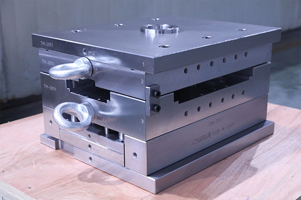
1 Core Logic and Industry Significance of Mold Base Size Calculation
Mold base size design must revolve around three core objectives: "adaptability, stability, and economy," with the calculation results directly affecting the overall performance of the mold. In actual production, excessive dimensional deviations may lead to cavity misalignment, ejector pin jamming, and other failures, while overly redundant dimensional design causes steel waste, excessive mold weight, and increased processing and transportation costs. For customers in the mold industry, mastering scientific calculation methods can both shorten mold development cycles and improve product molding pass rates, especially in high-precision mold fields such as automotive components and 3C products, where mold base dimensional accuracy is a core factor determining product quality.
1.1 Core Principles of Mold Base Size Calculation
Mold base size calculation must follow three core principles to ensure the design solution is both practical and scientifically sound.
1.1.1 Dimensional Adaptation Principle Matching the Mold Cavity
As the core of molding, the cavity's dimensions, quantity, and layout directly determine the basic dimensions of the mold base. Calculation should be based on the maximum external dimensions of the cavity, reserving sufficient installation space and guiding clearance—typically, the single-side clearance between the cavity and mold base plate needs to be controlled within 5-10mm. At the same time, consideration must be given to the force distribution of the cavity to avoid deformation of the mold base plate due to localized stress concentration. For example, for multi-cavity molds, the plate length and width must be calculated based on the cavity arrangement pattern (matrix, linear) to ensure uniform force distribution across all cavities.
1.1.2 Process Adaptation Principle Compatible with Processing Equipment
Mold base dimensions must match the technical parameters of processing equipment, including machine tool worktable dimensions, maximum clamping range, and travel distance. During calculation, it is necessary to confirm that the length and width dimensions of the mold base do not exceed the effective processing area of the machine tool worktable, the height dimension must meet the maximum spindle travel requirements of the machine tool, while also reserving space for fixture installation. Taking a vertical machining center as an example, the total height of the mold base should be less than 80% of the maximum spindle travel to avoid insufficient travel during processing.
1.1.3 Optimization Principle Balancing Strength and Cost
Mold base dimensions must find a balance between structural strength and production costs. Insufficient plate thickness can cause the mold to deflect under molding pressure, affecting product precision; conversely, excessively thick plates increase steel usage and processing time. During calculation, plate thickness must be verified through strength check formulas (such as the bending strength formula σ=My/Iz) to ensure that deformation under maximum molding pressure is controlled within the allowable range (typically ≤0.02mm), while prioritizing the selection of standard specification mold base components to reduce customization costs.
1.2 Practical Steps for Mold Base Size Calculation
Mold base size calculation must follow the logical process of "parameter collection - reference determination - component calculation - verification and optimization" to ensure precision at each step.
1.2.1 Preliminary Parameter Collection and Requirements Analysis
Before calculation, it is necessary to comprehensively collect core parameters, including cavity 3D model dimensions, density and molding pressure of the molding material (e.g., common molding pressure for injection molds is 15-35MPa), mold opening and closing stroke requirements, and installation space for ejection mechanisms. At the same time, the usage scenario of the mold must be clarified: whether it is a mass production mold or a trial production mold, and whether installation positions for accessories such as hot runners and sensors need to be reserved. These requirements will directly affect the mold base size design.
1.2.2 Cavity Layout and Reference Dimension Determination
Layout planning is carried out based on the number and dimensions of cavities to determine the basic length and width dimensions of the mold base. For a single-cavity mold, take the external dimensions of the cavity as the reference and add 10-20mm installation allowance in both length and width directions; for multi-cavity molds, calculate the total length and width based on the cavity spacing (typically ≥15mm to avoid gate interference). For example, with 4 cavities (single cavity length and width 100mm×80mm) arranged in a 2×2 matrix pattern and cavity spacing of 20mm, the basic length and width dimensions of the mold base plate would be (100×2+20×1)+20=240mm (length), (80×2+20×1)+20=200mm (width).
1.2.3 Calculation of Key Mold Base Component Dimensions
Core component size calculation includes plate thickness, guide pin and bushing specifications, ejector plate dimensions, etc. Plate thickness must be calculated considering cavity depth and molding pressure: moving plate thickness is typically 1.5-2.5 times the cavity depth, while fixed plate thickness is 1.2-2 times the cavity depth; guide pin length must cover the total plate thickness while reserving 5-10mm guiding allowance, with diameter selected according to standard specifications based on mold base dimensions (e.g., when mold base length/width ≤300mm, guide pin diameter should be 20-25mm); ejector plate dimensions must adapt to the moving plate, with length and width slightly smaller than the moving plate, and thickness sufficient to meet the installation strength requirements of ejector pins (typically ≥25mm).
1.2.4 Verification and Adjustment Optimization
After preliminary size calculation, multi-dimensional verification must be conducted: perform 3D assembly simulation using CAD software to check for interference between components; calculate the total weight of the mold base to ensure it does not exceed the maximum load capacity of processing equipment; adjust dimensions according to actual production requirements, such as appropriately increasing plate thickness for high-precision molds to enhance stability, or optimizing dimensions within strength limits for low-cost molds to save material.
1.3 Key Points for Size Calculation of Different Mold Base Types
Different types of mold bases, due to their structural characteristics, require emphasis on different key points in size calculation to ensure adaptation to specific application scenarios.
1.3.1 Size Selection and Fine-Tuning for Standard Mold Bases
Standard mold bases (such as LKM, HASCO series) have fixed specification parameters, with the core of calculation lying in selection and fine-tuning. The corresponding mold base model must be selected based on cavity dimensions and molding requirements (such as A plate thickness, B plate thickness, guide pin spacing, etc.), followed by fine-tuning of certain dimensions according to actual conditions—for example, when the plate length of a standard mold base is slightly less than required, the installation space can be compensated by increasing the thickness of spacer plates, avoiding the cost increase associated with changing the entire mold base model.
1.3.2 Customized Calculation Logic for Non-Standard Mold Bases
Non-standard mold bases require completely customized calculations based on mold requirements, with special focus on dimensional adaptation for special structures. For example, mold bases for two-shot molds need to reserve installation space for rotating mechanisms, requiring increased plate length and width during calculation to ensure the rotational components move without interference; for stack molds, the spacing between cavities on different levels and the total height must be calculated to balance molding efficiency and structural strength.
1.3.3 Dimensional Adaptation Techniques for Complex Cavity Mold Bases
For molds with complex cavities (such as deep cavities, irregular-shaped cavities), mold base size calculation needs strengthened strength verification. Deep cavity molds have significant cavity depth, requiring increased plate thickness and guide pin diameter to avoid offset deformation under molding pressure; irregular-shaped cavities have uneven force distribution, requiring finite element analysis software to verify stress concentration areas on the plates and appropriately increase local dimensions or add reinforcing ribs.
1.4 Common Calculation Mistakes and Avoidance Strategies
In mold base size calculation, design errors can easily occur due to parameter omissions or logical deviations, requiring targeted avoidance of common mistakes.
1.4.1 Calculation Deviation from Neglecting Cavity Force Distribution
Some designers only calculate mold base dimensions based on the external dimensions of the cavity, neglecting the force distribution characteristics of the cavity. For example, asymmetric cavities generate lateral forces under molding pressure; if guiding compensation space is not reserved in the mold base size design, it can lead to accelerated mold wear. Avoidance strategy: Use force analysis software to simulate the force situation on the cavity, and appropriately increase guide pin diameter or add auxiliary guiding mechanisms in directions with larger lateral forces.
1.4.2 Dimensional Errors from Ignoring Machining Allowances
Failure to consider machining allowances during calculation can result in mold base dimensions being too small to meet subsequent processing requirements. For example, plates requiring heat treatment and grinding, if 3-5mm machining allowance is not reserved, may result in final dimensions not meeting design requirements. Avoidance strategy: When calculating initial dimensions, reserve corresponding allowances based on processing technology; plates after heat treatment require an additional 2-3mm grinding allowance.
1.4.3 Cost Waste from Excessive Pursuit of Large Dimensions
Some designers, in pursuit of structural stability, blindly increase mold base dimensions, leading to increased steel usage and processing costs. For example, selecting oversized mold bases for small cavity molds not only increases production costs but also reduces processing efficiency. Avoidance strategy: Accurately calculate the minimum necessary dimensions through strength check formulas, prioritize standard specification components, and optimize dimensional design while meeting strength requirements.
Conclusion Section
The accuracy of mold base size calculation directly affects mold production efficiency, product quality, and comprehensive costs, representing an important manifestation of core competitiveness in the mold industry. Whether it is the selection and fine-tuning of standard mold bases or the customized design of non-standard mold bases, systematic planning combining cavity characteristics, processing equipment, and production requirements is essential. If you encounter challenges in mold base size calculation such as cavity layout optimization, strength verification difficulties, or adaptation of non-standard structures, please feel free to contact our technical team—with over 20 years of experience in mold base design, we can provide one-on-one precise calculation guidance and customized solutions, helping you shorten development cycles, reduce production costs, and achieve efficient coordination between mold design and production.